- Prior to commencement, refer to manufacturers recommended calibration procedure for this device. This is general terms for a pressure transmitter and in certain circumatances it may be the case that a characteristic of the instrument under test differs from this procedure.
- Check instrument against data sheet, P&ID and layout drawings.
- Record transmitter range. Output indication shall be calibrated with the transmitter. Record the instrument supply in.
- Simulate process variable that the device shall measure ie hydraulic or pneumatic pressure calibrator, temperature bath, manually move equipment, test solution for SG, ph or conductivity. Float type solution interface transmitters must be tested with suitable test fluid (simillar composition and SG). Suitable method of transport and handling the fluids must be provided. Determining the level in measurement chamber must be developed and agreed with the responsible engineer. Transmitter on oxygen service must be subject to pneumatic test only.
- Connect the output of transmitter to either the suitable test meter (electrical) or test gauge (pneumatic).
- By varying the simulated input signal incerasing and decreasing accordingly set zero and full scale to within the manufacturers tolerance.
- Apply varying simulated input 0%, 25%, 50%, 75%, and 100% and decreasing back to 0%
- Calculate percetage error if applicable
- Reinstate the device and check installation detail, sign and date accordingly.
- Attached any "As Built" drawings or sketches. must be stamped "As Built" and signed/date both in red ink.
- Record any defect and deviation on data sheet and sign off ITRs as complete by printing and signing name and date in "Inspected by section"
Thursday, June 25, 2009
Analog transmitter calibration
Tuesday, June 23, 2009
Power & Control Cable Pre-commissioning
Cek dan Pastikan
- Compare cable size, type and tagging with the cable schedule. Ensure core identification match with connection diagram and phase sequence
- Check the glands certificate meet the area classification as mentioned in spec
- Inspect the glands cable for tighness and good workmanship; correct type and size of cable installed. Check the outdoor glands have been wrappen in vulcanising tape
- Ensure the gland plates for all single cables have been manufactured from non magnetic materials
- Pastikan conductors are terminated using crimped connections. check correct size and type of crimping lugs has been used
- Before making any measurement, inspector should ensure both ends of the cable has been disconnected and are clear of any metal
- Cek the earth connection
Insulation Resistance Test
For LV multicore measurement shall be
- core to core
- core to earth
- screen to armour

Switchgear Pre-commissioning
Switchgear pre-installation inspection
- Pastikan equipment certificate meet area classification requirement
- Remove temporary weather proofing, transport packing, and silica gel drying agent from switchgear, Cek cleanliness di dalam switchgear, specially for insulator
- Compare switchgear equipment meets equipment schedule, specially rating and any circuit changes
- Pastikan equipment meets spec, including weather, dust and vermin proofing
Switchgear post-installation inspection
- Check switchboard assy for alignment, level, tighteness foundation bolts and fixing in general
- Pastikan all panel doors and gland plate are bonded to switchboard structure
- Pastikan all equipment installed in switch board are in good conditions
- Inspect busbar joint
- Pastikan all insulators are clean, free from damage and not subjected to undue mechanical stress
- Cek all items corresponded to material list
- Cek all damages items
- Clearence phase to phase and phase to earth are acordance with spec
- Section clearances are satisfactory
- Earthing connection connected to all necessary points and clear of other metal
- Earthing connection tight, greased and thinned as required. Inspect the switchboard earth bar and earth cable for electrical and mechanical continuity
- Confirm all earth runs connected to main grid
- Labels correct/fitted
- Manufacturers name plate/marker correct/fitted
- Serial numbers match manufacturers test certificates
- Primary connection assembly /jointing compound, no undue stress/tension on equipment, fitting bolt correctly tensioned
- No dissimilar metals employed on primary connections
- No rust on equipment
- Site surfacing is correct and satisfactory
- All fixing bolts are tight
- No leaking impregnation fluid or swelling of containers
- Ensure all manufacturer's document and test certificate have been received
- Operation of locking facilities
- Cable entry arrangments
- Ensure all equipments meet specification weather, dust and vermin proofing after installation
- Examine fuses for rupturing or signs of deterioration
Switchborad testing
- After all busbar joints are completed but prior to securely fitting busbar covers, measure insulation resistance of the busbars and control wiring.
- Where there are any busbar joints, ductor test must be carried out prior to fitting covers. Simillar joints shall have a contact resistance within 10% of each other. The joints shall have a resistance equal or lower than an equivalent section of busbar
- Test switch board earth system for electrical dan mechanical continuity. Measure earth path resistance at the earth bar to the general earth system and earth bar joints
- Ensure that all protection relay have been tested accrdance with requirement of appropriate test certificate and vendor instruction
- Measure insulation testing of busbar and control wiring. Test should be carrued out prior to pressure test and before energising switchboard. Minimum acceptabe test result as below. A Power frequency voltage test (pressure test) on both main and outgoing cicuits sall be carried out phases and phases to earth.

Following conection shall be adhered for the tests
- All secondary sides of current transformers shall be short circuit
- All secodary sides of voltage transformer shall be open circuit
upon completion all tests, reconnect all cables and ensure that shorting links and fuses are replace
Monday, June 22, 2009
Electrical & Instrument Fabrication & shop Drawing
What kind of electrical and instrument drawing can be found in fabrication of an oil and gas fabrication project. This only an overview and few drawing samples for who wants to know about a project fabrication -construction, specially for electrical and instrument disciples area. Actually quantity and kinds of drawing are depend on system which are already designed and approved by Engineering and client or project owner.
Dalam suatu project construction biasa kita temukan istilah EPCI. Biasa setelah bidding project selesai, maka akan di announce pemenang project. Missal untuk engineering dan procurement di menangkan oleh PT A, untuk fabrikasi dimenangkan oleh PT B, untuk offshore installation dimenangkan oleh PT C. Tapi ada juga untuk EPCI ini dimenangkan oleh satu perusahaan.
E stands for Engineering,
Engineering is body/company who have designed a project. Here will be discussed and decided about a system made, material consumed, manpower required included skill and competency, method agreed, machine used and how to manage activities and communication flow among discipline, management, contractor, client, owner, third parties inspection and classification
P is Procurement,
Normally procurement is how to procure after dealing with supplier and vendor material and schedule delivery and receiving and where are put ; warehouse or need certain condition reservation
C is Construction,
Construction is done in site, usually in a yard. Normally yard is located in seashore in order easy to bring product CPP or modules to offshore installation location. First maybe preparation of civil and foundation activities, than structural installation, piping installation, electrical installation and instrument installation, and lastly pre commissioning.
I is Installation,
After fabrication finished, next stage is installation. the product will be pulled to edge of sea and put on the barge and do sea fastening and ready to sail away to installation place. During this time shall be prepared all items for offshore installation, lifting equipment capacity, competent crews, scenario of installation etc
Sekarang kita jump to topic about Electrical & instrument drawing. Actually each client or owner or company have their specification. They have their own terminology like few companies use term “grounding” ,others use term “earthing”. All terminologies actually are agreement in specification /datasheet/manufacturing sheet. All depend how they define and name in their document
ELECTRICAL DESIGN DRAWING
Electrical/PAGA/Navigational Aid index, legend, symbol & notes
Electrical/PAGA/Navigational Aid single line diagram or one line diagram
lectrical/PAGA/Navigational Aid block diagram
Electrical/PAGA/Navigational Aid schematic/logic/loop/wiring/interconnection diagram
Electrical/PAGA/Navigational Aid layout
Electrical/PAGA/Navigational Aid installation Details
Electrical/PAGA/Navigational Aid cable/panel Schedule
Electrical main tray/ladder support detail
Hazardous area classification
Electrical design miscellaneous
ELECTRICAL SHOP AND INSTALLATION (Field Run) DRAWING
Electrical power routing layout
Electrical Power tray support layout
Electrical Power tray support detail
Electrical Power mounting support layout
Electrical Power mounting support detail
Electrical Equipment support layout
Electrical Equipment support detail
Lighting cable routing
Lighting tray support layout
Lighting tray support detail
Lighting mounting support layout
Lighting mounting support detail
Navigation aid mounting support layout
Navigation aid mounting support Detail
PAGA cable tray support layout
PAGA cable tray support detail
PAGA mounting support layout
PAGA mouting support detail
Electrical/PAGA cable penetration layout
Electrical/PAGA cable penetration detail
Electrical Shop Miscellaneous
INSTRUMENT DESIGN DRAWING
Instrument/ Fire & Gas/Telecommunication index, legend, symbol & notes
Instrument process cause & effect diagram
Instrument safety cause & effect diagram
Instrument shutdown hierarchy diagram
Instrument blok diagram
Instrument interconnection/loop /termination/wiring/interface/schematic/logic diagram
Instrument layout
Instrument installation/support/mounting detail
Instrument hook up
Instrument cable/tubing/panel schedule
Instrument level sketches
Instrument main tray/ladder support detail
Instrument miscellaneous
Fire and Gas cause & effect diagram
Fire and Gas single line/interconnection/loop diagram /termination/
Fire and Gas wiring/interface/schematic/logic diagram
Fire and Gas block diagram
Fire and Gas layout
Fire and Gas installation/mounting detail
Fire and Gas miscellaneous
Safety Escape route/sign layout
Telecom single line diagram
Telecom /interconnection/loop diagram /termination/wiring/logic diagram
Telecom cable routing layout
Telecom block diagram
Telecom layout
Telecom installation/mounting detail
Telecom miscellaneous
INSTRUMENT SHOP/INSTALLATION DRAWING
Instrument mounting support layout
Instrument installation detail
Instrument tubing routing
Instrument tubing tray support Layout
Instrument tubing tray support detail
Instrument cable tray support Layout
Instrument cable tray support detail
Fusible plug mounting layout
Fusible plug detail
Fusible plug tray support Layout
Fusible plug tray support detail
Fire & Gas mounting support layout
Fire & Gas mounting support detail
Fire & Gas cable tray support layout
Fire & Gas cable tray support detail
Telecom mounting support layout
Telecom mounting support detail
Telecom cable tray support layout
Telecom cable tray support detail
Instrument Tubing/cable Penetration layout
Instrument Tubing/cable Penetration Detail
Instrument Junction Box Support layout
Instrument Junction Box Support Detail
Few drawing samples for Electrical Discipline :
1. Legend. Legend tells all symbols which are used in drawing in order whoever read drawing can understand everything on drawing
There are several national and international standards for graphical symbols in circuit diagrams, in particular:
· IEC 60617 (also known as British Standard BS 3939)
· ANSI standard Y32 (also known as IEEE Std 315)

2. Single line diagram. Ada juga memakai istilah one line diagram. Ini biasa nya men deskripsi kan tentang aliran daya listrik, start from generator, bus duct, switchgear, transformer, ke distribution board, than supply untuk
- motor /pump/ fan/ compressor
- space heater
- lighting
- fire and gas panel
- Public address and general alarm panel
- Telecommunication panel
- Instrument supply panel etc

3. Block diagram. Di dalam block diagram biasa nya menggambarkan interrelationship among system and existing equipment in global view, usually for electrical about cabling relationship. Below are lighting block diagram sample

4. Wiring diagram/Interconnection diagram/loop diagram/schematic diagram. so far I have found They are almost same. All are about wiring or cabling detail for real connection. All connection should be labeled by tag no or cable marker for tracking and identification. Below are samples of Junction box

and turbine-generator wiring connection.

5. Plan or layout drawing. Plan show location of equipment. Plan usually base on system. E.g. lighting plan, fire and gas plan, public address and general alarm plan, telecommunication plan, navigational aid plan. Below is sample of fire and gas plan

6. Detail installation drawing. These are detail installation for each equipments or detector or sensor which are given in plan drawing included with each bill of material for each installation. So each plan drawing will have all kinds of detail installation for all equipments /detectors /sensor which are put in plan drawing. Below is sample of strobe light installation detail

Few drawing samples Untuk Instrument Discipline
1. Instrument hook up. Hook up is similar with installation detail. See below picture

2. Instrument Tray support detail. This tells about support of main tray or ladder

3. Instrument layout. This give information about location of instrument in the field

5. Instrument Fusible plug plan & detail

Monday, March 16, 2009
Electrical Hook up general note for instrument installation

- Instrument hook up and installation for instrument wiring system shall be accordance with specifications (Instrument design basis & instrument installation specification)
- The hook up and installation drawings shown in general the required position of the instrument relative to measuring point. The exact location shall be determined at the site with the aid of instrument location drawings
- All instruments shall be installed in such a way that they are not subjected to
- Unable to access
- excessive vibration
- extreme environment conditions
- obstruct traffic
- periodic maintenance of adjacent equipmentbe installed in place which are prone to leakage/dripping - Sufficient space shall be left around the instrument for instrument cover removal /withdrawal and for removal protective shades. The minimum clearance between any parts and instrument and surrounding structures or equipment shall not be less than 0.2m to allow insulation, painting, etc
- Sufficient flexibility shall be provided in instrument cable line to allow thermal expansion the line equipment to which they connect
- All fabricated work in the field shall be grounded smooth and painted as per project standards. All painting shall be carried out before attachment of instruments, cables, tubing, etc. to the painted materials
- All instrument cables and wiring shall be identified with the drawings and as detailed in instrument basis. Instrument cable shall be tagged with 316SS tags at walls, penetration and at the end points
- Wiring to terminal blocks shall not exceed two connections per terminal point
- A short coil of cable shall be made in field cable at instrument
- Every wire in every cable including spare wires and drain wires shall be terminated with a company approved insulated ferule, on rail mounted terminal blocks , at both end
- Each terminal point (including end devices, junction boxes and marshalling strips) shall be made up to include heat shrink insulation over cable and wire shields, end and bare drain wires
- All cable shields shall be earthed at IER (Instrument Equipment Room) and CCR (Control Center Room) only. Individual shields drain wires for pairs and triad shall be cut, coil and taped at the instrument head
- All multi core pair and triad overall shields and drain wires shall be insulated green/yellow colored PVC sleeving
- All metallic components, others than current carrying conductors shall be connected to a common earth system. All unused cable cores shall be earthed at one end only
- cable runs that penetrate walls (E.G. building walls, blast walls and fire walls) that separate safe area hazardous (classified) shall be provided with vapor tight cable transits fire rated to meet the fire wall requirements
Wednesday, March 11, 2009
Generator Electrical Protective Relay Devices base on ANSI

Over excitation protection Volt/Hertz relay (ANSI No.24)
Relay ini harus di-set untuk meng-counter high induction
proporsional dengan V/f, yang mengakibatkan thermal
overloading. These may occur during starting and shut
Relay ini harus di-set untuk meng-counter high induction
proporsional dengan V/f, yang mengakibatkan thermal
overloading. These may occur during starting and shut
Picture :
ABB-product series-compact and integrated with multi protectiondown under full load condition
Under voltage relay (ANSI No.27)
This relay prevents generator/motor to operate below normal voltage/frequency operating system cause by AVR or internal faults. Time delay must be set slower than transient system voltage dip and must be faster than too much slowing down generator and make re accelerate to meet proper plant recovery
Reverse power relay (ANSI No. 32)
This device protects generator to receive power from system in case of failing prime mover to drive generator. Turn back power may damage generator.
Lost of excitation relay (ANSI No. 40)
Faulty in generator field excitation circuitry causes generator loss of excitation. In this case generator will act as induction generator which received reactive power from system. This condition will make instability in power system and over heating on damper rotor windings
Negative sequence relay (ANSI No.46)
These are included to detect phase unbalance, phase reversal, and phase sequence fault. These abnormal condition will heat machine windings. This kind of relay is more independent to do close/open power system
Inadvertent energizing relay (ANSI No. 50/27)
Due to unintentionally energizing will make generator damage. This relay will limit down possibility of generator damage. Actually this relay is combination of over current relay and under voltage relay with controlling electronic digital logic.
Breaker failure relay (ANSI No.50BF)
In the event of a downtimes or faulty in generator, generator can remain online if the breaker is defective or substantial damage. This protection will measure minimum breaker current and thru auxiliary contact. It can be activated via internal protective tripping or externally via binary input
Sensitive earth fault relay (ANSI No.50/51G)
This device is for Limiting damage of generator in the event of rotor earth fault. The sensitive earth fault can be use as separate earth fault protection
Definite time over current relay (ANSI No.50/51)
This is short circuit protective device
Inverse time over current relay (ANSI No 51V)
This is also short circuit protective device with ANSI and IEC curve characteristic respond. This can be selected base on system requirement
Over voltage relay (ANSI No.81U)
This protect generator voltage regulator that could be damaged in an over voltage condition due to AVR failure or manual voltage control errors. A time delay is provided to prevent tripping under transient voltage spikes
Monday, February 2, 2009
Fire Type
Fire can be classified base on fuel source type. Actually different fuel will be come out different fire characteristic. Base on this, fire detector/gas detector should be suit with the actual source of fuel which might likely involveded in a system of process/equipment/utility
below are picture some of fire pictures based on different source of gas
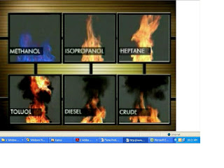
below are picture some of fire pictures based on different source of gas

Subscribe to:
Posts (Atom)